I think the discussion regarding machinery weight may have overlooked a anothef advantage of three shaft arrangement compared to a four shaft arrangement in a warship.
A three shaft arrangement places the wing shafts significantly closer to the centerline. This significantly reduces the length of the shaft that must run through the side torpedo protection system to emerge from the hull, and also reduces the necessary length of the portion of the wing shaft outside the hull. This both reduces the vulnerability the wing shafts to direct underwater hits, and length of torpedo protection system compromised by shaft alley running through it.
There are no 4 shaft ships with recipricating engines I know of. The first 4 shaft ship was HMS Dreadnought, with her new fangled steam turbine propulsion. 4 shafts was natural for early direct drive steam turbines because without reduction gearing the turbines have to be large in order to generate the necessary power at a low enough RPM that would not cause the propellers to cavitate too much. So it is convenient for layout to have large high pressure turbine and low pressure turbines in different engine rooms driving separate shafts, resulting in 2 sets of turbines driving 4 shafts. In this case three shaft arrangement would be more awkward from engine room layout perspective. But the Germans still opted for 3 shafts with their first steam turbine powered dreadnoughts. This strongly suggest the Germans put a higher premium on the protective advantages of three shaft layout over layout advantages of a 4 shaft arrangement.
3-shaft propulsion
Moderator: Bill Jurens
-
Steve Crandell
- Senior Member
- Posts: 954
- Joined: Wed Feb 05, 2014 7:05 pm
Re: 3-shaft propulsion
You could also look at the Montana/Midway powerplant layout. They have a four shaft arrangement where the after engine rooms power the outboard shafts and the forward engine rooms power the inboard shafts. This results in an arrangement where the long shaft runs go down the ship's centerline instead of the ship's side protective system.
-
marcelo_malara

- Senior Member
- Posts: 1852
- Joined: Sun Oct 02, 2005 11:14 pm
- Location: buenos aires
Re: Battleship Bismarck: A Design and Operational History
Hi! No, I do not have much detailed data to compare exactly the same components.chuckfan3@gmail.com wrote: ↑Thu Jan 11, 2024 5:04 am
Do those weight measures normalize for differences in auxiliary machineries, differences in weight caused by differences in machinery layout stipulated to meet other requirements, such as compartmentalization and unitized arrangement? If not, then they don;t accurately reflect the raw weight efficiency of the power plant in generating propulsive power.
Regards
-
chuckfan3@gmail.com
- Member
- Posts: 30
- Joined: Fri Nov 24, 2023 6:56 pm
Re: 3-shaft propulsion
Doesn’t matter where the outboard engine rooms are along the length of the ship. The outboard shafts in a 4 shaft arrangement are farther away from centerline than the outboard shafts in a 3 shaft arrangement, so the length of shaft that must run through the TDS to go from engine room to the sides of the ship would have been longer in a 4 shaft arrangement than in a 3 shaft arrangement for any given hull form. Similarly, the run of the shaft outside the hull for the wings shafts in a 4 shaft arrangement must also be longer to give the outboard propellers the same hull clearanceSteve Crandell wrote: ↑Thu Jan 11, 2024 12:19 pm You could also look at the Montana/Midway powerplant layout. They have a four shaft arrangement where the after engine rooms power the outboard shafts and the forward engine rooms power the inboard shafts. This results in an arrangement where the long shaft runs go down the ship's centerline instead of the ship's side protective system.
-
Steve Crandell
- Senior Member
- Posts: 954
- Joined: Wed Feb 05, 2014 7:05 pm
Re: 3-shaft propulsion
It obviously does matter, because the closer the engine rooms are to the stern, the fewer TDS bulkheads are pierced by the shafts.chuckfan3@gmail.com wrote: ↑Thu Jan 11, 2024 5:38 pmDoesn’t matter where the outboard engine rooms are along the length of the ship. The outboard shafts in a 4 shaft arrangement are farther away from centerline than the outboard shafts in a 3 shaft arrangement, so the length of shaft that must run through the TDS to go from engine room to the sides of the ship would have been longer in a 4 shaft arrangement than in a 3 shaft arrangement for any given hull form. Similarly, the run of the shaft outside the hull for the wings shafts in a 4 shaft arrangement must also be longer to give the outboard propellers the same hull clearanceSteve Crandell wrote: ↑Thu Jan 11, 2024 12:19 pm You could also look at the Montana/Midway powerplant layout. They have a four shaft arrangement where the after engine rooms power the outboard shafts and the forward engine rooms power the inboard shafts. This results in an arrangement where the long shaft runs go down the ship's centerline instead of the ship's side protective system.
-
chuckfan3@gmail.com
- Member
- Posts: 30
- Joined: Fri Nov 24, 2023 6:56 pm
Re: 3-shaft propulsion
Steve Crandell wrote: ↑Thu Jan 11, 2024 7:45 pmIt obviously does matter, because the closer the engine rooms are to the stern, the fewer TDS bulkheads are pierced by the shafts.chuckfan3@gmail.com wrote: ↑Thu Jan 11, 2024 5:38 pmDoesn’t matter where the outboard engine rooms are along the length of the ship. The outboard shafts in a 4 shaft arrangement are farther away from centerline than the outboard shafts in a 3 shaft arrangement, so the length of shaft that must run through the TDS to go from engine room to the sides of the ship would have been longer in a 4 shaft arrangement than in a 3 shaft arrangement for any given hull form. Similarly, the run of the shaft outside the hull for the wings shafts in a 4 shaft arrangement must also be longer to give the outboard propellers the same hull clearanceSteve Crandell wrote: ↑Thu Jan 11, 2024 12:19 pm You could also look at the Montana/Midway powerplant layout. They have a four shaft arrangement where the after engine rooms power the outboard shafts and the forward engine rooms power the inboard shafts. This results in an arrangement where the long shaft runs go down the ship's centerline instead of the ship's side protective system.
no, engine room has to be inboard or TDS. placing engine room farther to the rear reduces number of transverse bulkheads inboard of the TDS that must be pieced by shaft alley, but it doesn’t affect how much of the shaft alley has to be inside the TDS itself.
-
chuckfan3@gmail.com
- Member
- Posts: 30
- Joined: Fri Nov 24, 2023 6:56 pm
Re: 3-shaft propulsion
Steve Crandell wrote: ↑Thu Jan 11, 2024 7:45 pmIt obviously does matter, because the closer the engine rooms are to the stern, the fewer TDS bulkheads are pierced by the shafts.chuckfan3@gmail.com wrote: ↑Thu Jan 11, 2024 5:38 pmDoesn’t matter where the outboard engine rooms are along the length of the ship. The outboard shafts in a 4 shaft arrangement are farther away from centerline than the outboard shafts in a 3 shaft arrangement, so the length of shaft that must run through the TDS to go from engine room to the sides of the ship would have been longer in a 4 shaft arrangement than in a 3 shaft arrangement for any given hull form. Similarly, the run of the shaft outside the hull for the wings shafts in a 4 shaft arrangement must also be longer to give the outboard propellers the same hull clearanceSteve Crandell wrote: ↑Thu Jan 11, 2024 12:19 pm You could also look at the Montana/Midway powerplant layout. They have a four shaft arrangement where the after engine rooms power the outboard shafts and the forward engine rooms power the inboard shafts. This results in an arrangement where the long shaft runs go down the ship's centerline instead of the ship's side protective system.
no, engine room has to be inboard or TDS. placing engine room farther to the rear reduces number of transverse bulkheads inboard of the TDS that must be pieced by shaft alley, but it doesn’t affect how much of the shaft alley has to be inside the TDS itself. that is controlled by how far inboard is the shaft itself.
here 3 shaft arrangement lets the wing shaft be further inboard so less make it compromising to the TDS.
-
chuckfan3@gmail.com
- Member
- Posts: 30
- Joined: Fri Nov 24, 2023 6:56 pm
Re: 3-shaft propulsion
Bill Jurens wrote: ↑Thu Aug 15, 2019 5:25 pm For some reason the number three does not seem to work well regarding propulsion systems. Number of three-legged animals? Pretty small, perhaps non-existent. Number of three-engined airplanes? Not many left of those. Number of three-wheeled automobiles? Again, not too many. Number of three-engined ships? They seem to have more-or-less died off, too.
This suggests the presence of some underlying 'natural law', but I haven't seen it articulated as such anywhere...
Bill Jurens
in airplanes, engines impose their own drag penalty. so fewer engines the better, so long as the engines are powerful enough to give the plane the desired performance and reliable enough to diminish the benefit of redundancy. this is why both quad jets and tri-jets are increasingly uncommon, leaving twin jets dominant in commercial aviation. A three engine arrangement has an additional disadvantage in commercial aviation because the center engine has to be in the fuselage, either at the nose or at the tail. This creates more cabin noise than twin or quad engine where all the engines are outside the fuselage.
-
Bill Jurens
- Moderator
- Posts: 878
- Joined: Mon Oct 18, 2004 4:21 am
- Location: USA
Re: 3-shaft propulsion
In a very general sense, one larger propeller turning slowly will be more efficient than any larger number of propellers turning more rapidly. The optimum number of propellers, and their size, is largely driven by issues of geometry -- draft is limited after all -- and the perceived need for redundancy in the engineering plant.
Bill Jurens
Bill Jurens
-
Byron Angel
- Senior Member
- Posts: 1658
- Joined: Sun Mar 06, 2011 1:06 am
Re: 3-shaft propulsion
Bill Jurens wrote: ↑Fri Jan 12, 2024 5:28 pm In a very general sense, one larger propeller turning slowly will be more efficient than any larger number of propellers turning more rapidly. The optimum number of propellers, and their size, is largely driven by issues of geometry -- draft is limited after all -- and the perceived need for redundancy in the engineering plant.
Bill Jurens
On the road presently, but just popping in to support Bill’s comment. Same was also true with respect to WW1 fixed-pitch aircraft propellers. Larger diameter slower revolving props of appropriate pitch were found to be most efficient.
One related aspect, which I do not claim to fully understand, is that different pitches (perhaps at different rpm’s) could selectively enhance certain aspects of an aircraft’s performance. The Fokker Triplane was said to have been initially fitted with a “speed prop”, later replaced with a “ climb prop”.
B
-
marcelo_malara
- Senior Member
- Posts: 1852
- Joined: Sun Oct 02, 2005 11:14 pm
- Location: buenos aires
Re: 3-shaft propulsion
Hi Byron. This is related to the angle of attack as felt by the blade. The blade is just a rotating wing. In the graph:Byron Angel wrote: ↑Wed Apr 17, 2024 2:38 pmBill Jurens wrote: ↑Fri Jan 12, 2024 5:28 pm In a very general sense, one larger propeller turning slowly will be more efficient than any larger number of propellers turning more rapidly. The optimum number of propellers, and their size, is largely driven by issues of geometry -- draft is limited after all -- and the perceived need for redundancy in the engineering plant.
Bill Jurens
On the road presently, but just popping in to support Bill’s comment. Same was also true with respect to WW1 fixed-pitch aircraft propellers. Larger diameter slower revolving props of appropriate pitch were found to be most efficient.
One related aspect, which I do not claim to fully understand, is that different pitches (perhaps at different rpm’s) could selectively enhance certain aspects of an aircraft’s performance. The Fokker Triplane was said to have been initially fitted with a “speed prop”, later replaced with a “ climb prop”.
B
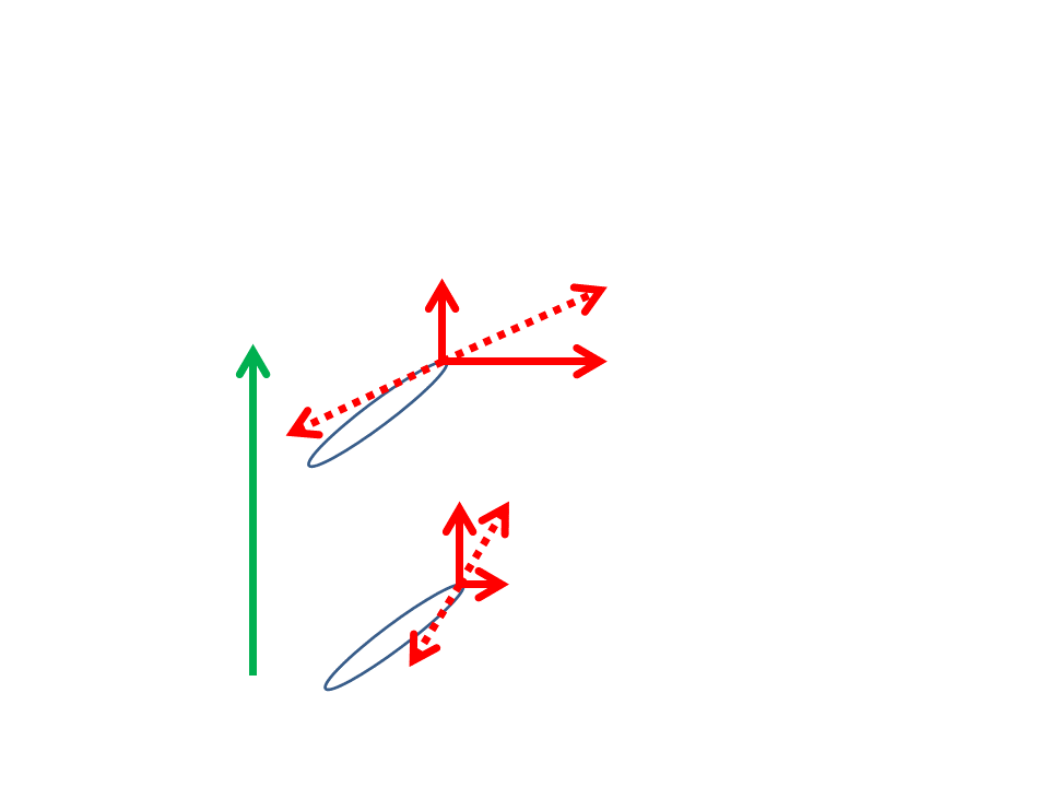
-green vector of motion of the airplane
-solid red, one vector represents the forward movement of the blade due to its being attached to the airplane, and the other the rotating movement due to the engine
-dotted red, the vector resultant of the sum of the two solid red vectors, and the opposite, the vector representing the flow of the air as seen by the blade.
As seen, a positive angle of attack is needed for the blade to "lift" in the forward direction. But this angle of attack should be within limits:
-so the propeller will not stall if the angle of attack is too large
-that the angle would minimize the drag of the turning moment
In the case of the Fokker you mentioned, I presume that a large angle of attack is used for speed, and a lower angle for climbing, just as the use of low gear in a car for a climbing road, and a high gear on a plain road.
Re: 3-shaft propulsion
Thank you!Alberto Virtuani wrote: ↑Fri Aug 09, 2019 4:31 pm Hi Thorsten,
from what I read in your posted table (http://www.kbismarck.org/forum/download ... hp?id=3574.html), it looks very unlikely that the twins could achieve the 32 knots (something around 190000 shp would be needed). Which displacement these data refer to for Gneisenau ? Sorry if my question is stupid but I don't speak German at all and possibly this info is already in the header of the table....
AFAIK, Scharnhorst achieved 32 knots at trials developing the 166500 shp in extra power (probably at a light displacement) but Gneisenau KTB reports 32 knots during the chase of HMS Glorious at operative displacement.....
Bye, Alberto
-
Byron Angel
- Senior Member
- Posts: 1658
- Joined: Sun Mar 06, 2011 1:06 am
Re: 3-shaft propulsion
marcelo_malara wrote: ↑Wed Apr 17, 2024 4:03 pmHi Byron. This is related to the angle of attack as felt by the blade. The blade is just a rotating wing. In the graph:Byron Angel wrote: ↑Wed Apr 17, 2024 2:38 pmBill Jurens wrote: ↑Fri Jan 12, 2024 5:28 pm In a very general sense, one larger propeller turning slowly will be more efficient than any larger number of propellers turning more rapidly. The optimum number of propellers, and their size, is largely driven by issues of geometry -- draft is limited after all -- and the perceived need for redundancy in the engineering plant.
Bill Jurens
On the road presently, but just popping in to support Bill’s comment. Same was also true with respect to WW1 fixed-pitch aircraft propellers. Larger diameter slower revolving props of appropriate pitch were found to be most efficient.
One related aspect, which I do not claim to fully understand, is that different pitches (perhaps at different rpm’s) could selectively enhance certain aspects of an aircraft’s performance. The Fokker Triplane was said to have been initially fitted with a “speed prop”, later replaced with a “ climb prop”.
B
-green vector of motion of the airplane
-solid red, one vector represents the forward movement of the blade due to its being attached to the airplane, and the other the rotating movement due to the engine
-dotted red, the vector resultant of the sum of the two solid red vectors, and the opposite, the vector representing the flow of the air as seen by the blade.
As seen, a positive angle of attack is needed for the blade to "lift" in the forward direction. But this angle of attack should be within limits:
-so the propeller will not stall if the angle of attack is too large
-that the angle would minimize the drag of the turning moment
In the case of the Fokker you mentioned, I presume that a large angle of attack is used for speed, and a lower angle for climbing, just as the use of low gear in a car for a climbing road, and a high gear on a plain road.
Thanks, Marcelo! Makes perfect sense.
Byron